Home Page Our Blog Maximum Length for Infeed Grinding (Centerless)

Contact us for help?

Contact with us through our representative or submit a business inquiry online.

Contact Us

Maximum Length for Infeed Grinding (Centerless)

Medical Oxygen Generator Plant


Maximum Length for Infeed Grinding | Scarlo Machines

Maximum Length for Infeed Grinding (Centerless)


Introduction

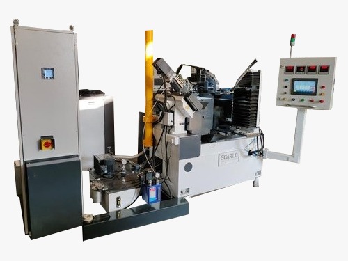
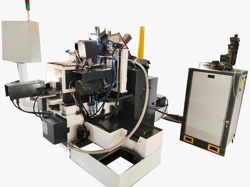
Understanding the maximum length for infeed (plunge) centerless grinding is crucial for accuracy, surface finish, and process stability. In infeed grinding, the part is located between the grinding and regulating wheels with shoulders or profiles that prevent axial movement. As a practical rule, the part length should not exceed the effective wheel width, allowing side clearances for chamfers, run-out, and dressing wear.


Description

In infeed grinding, the workpiece is plunged into a set wheel gap and supported on a work-rest blade. Because the part is blocked axially by its shoulders or profile, the maximum grindable length is governed by the grinding wheel width (GW) and any relief required on both sides. A typical guideline is:

Max part length ? GW ? (total side clearance) where side clearance is generally 3–6 mm per side depending on shoulder geometry, corner radii, and stock removal. Longer parts may require a wider wheel, relief grooves, center dressing strategies, or process re-engineering.


Applications and Benefits

Applications Benefits
  • Plunge grinding of shafts with step/shoulder features
  • Valve, pin, and roller components requiring controlled shoulders
  • Bearing races and precision bushings with tight tolerance zones
  • Medical and aerospace parts with form/relief profiles
  • Toolroom trials to validate wheel width vs. component length
  • Predictable sizing and roundness with stable part support
  • Reduced chatter by keeping length within effective wheel face
  • Improved surface finish from correct wheel engagement
  • Lower scrap by allowing side clearance for edge break and run-out
  • Faster setups by using a clear length-to-wheel guideline

Key Factors That Limit Maximum Length

  • Grinding wheel width (GW): Primary determinant; part length should be ? GW minus clearances.
  • Shoulder geometry: Sharp corners need extra allowance; chamfers/radii reduce edge loading.
  • Work-rest blade setup: Height, angle, and blade wear affect stability on longer parts.
  • Regulating wheel settings: Speed, inclination, and feed force influence axial control.
  • Dressing pattern & wear: Tapered faces or worn edges reduce effective width.
  • Material & stock removal: Harder alloys or heavy stock may require more side clearance.
  • Coolant delivery: Proper flood into the nip zone stabilizes temperature on long faces.
  • Run-out/lead-in grooves: Relief grooves can allow the part to slightly exceed GW in special cases.

Where These Guidelines Are Used

  • Automotive: Infeed grinding of gearbox pins, injector components, and differential rollers.
  • Manufacturing Plants: Precision plunging of stepped shafts and sleeves in mass production.
  • Aerospace & Medical: Tolerance-critical forms where axial locking is necessary.

Why Choose Us?

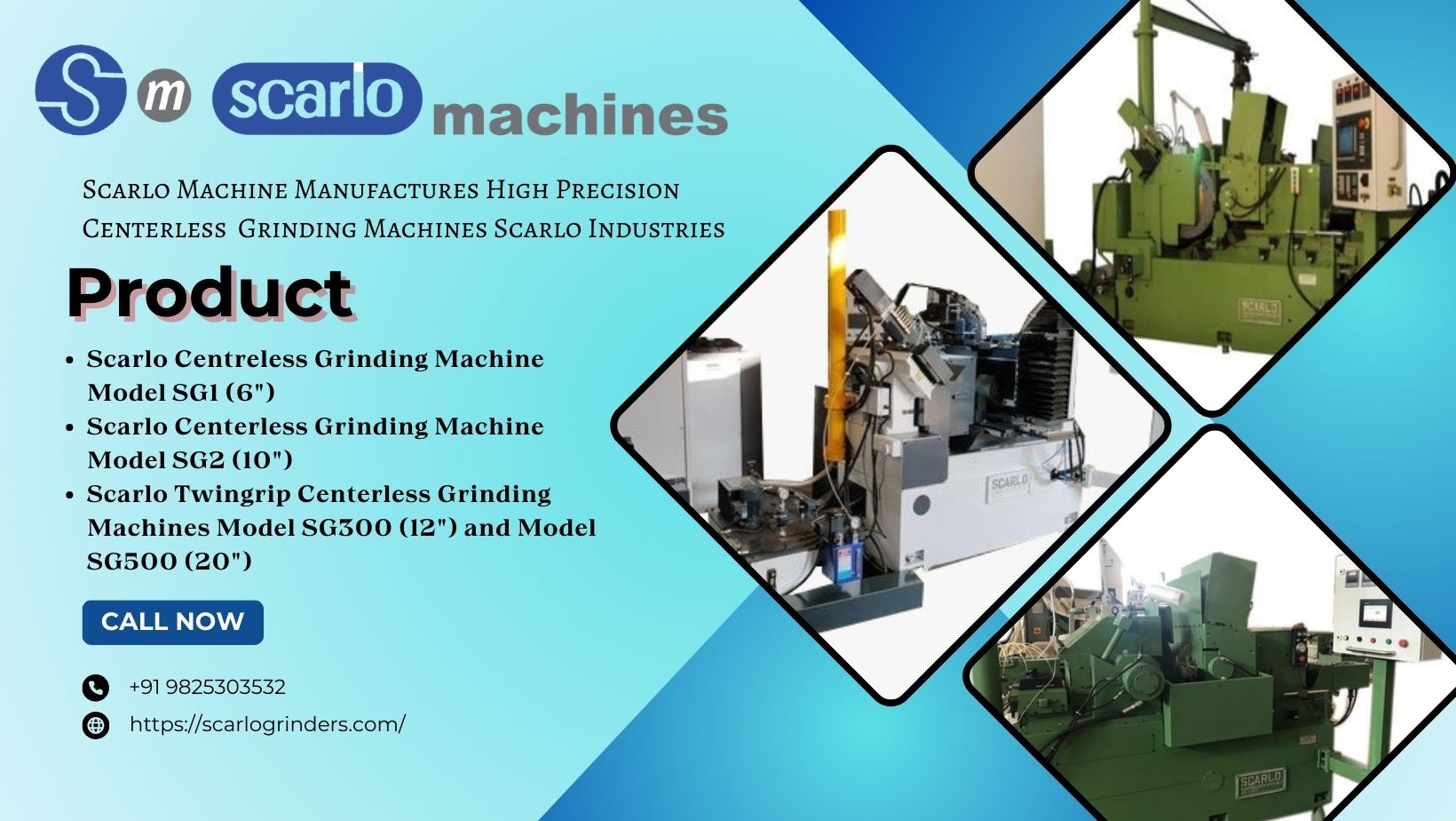
At Scarlo Machines, we help you determine the optimal infeed length vs. wheel width for your components, selecting correct wheel specifications, blade geometry, and dressing strategies. Our decades of process expertise ensure stable setups, superior finish, and repeatable tolerances for complex shoulders and form grinds.


Uses & Importance

Setting the right maximum infeed length improves roundness, minimizes thermal distortion, and prevents edge burning. By aligning part length with effective wheel width—and maintaining adequate side clearance—you achieve faster cycles, fewer rejects, and consistent quality across batches.


Manufacturer & Supplier Information

Scarlo Machines is a trusted centerless grinding solutions partner offering machines, tooling, and application support for infeed and thrufeed operations. We guide customers on wheel width selection, part length limitations, and fixture setup to achieve best-in-class accuracy and productivity.

FAQs

1. Can the part length exceed the grinding wheel width in infeed grinding?
Generally, no. In infeed (plunge) grinding the part is axially blocked by shoulders, so length should be within the effective wheel face, allowing 3–6 mm clearance per side. Special cases use relief grooves or tapered dress to manage slight overhang.
2. How do I estimate the maximum infeed length quickly?
Use a rule of thumb: Max length ? GW ? (side clearance × 2). Start with 3–6 mm per side depending on shoulder radius, stock removal, and wheel wear, then validate with a short trial pass.
3. Does thrufeed follow the same limit?
No. In thrufeed, parts can be longer than the wheel width because they traverse across the wheel face. The infeed limit is specific to plunge operations where the part is stationary axially.
4. What if I must grind a longer shoulder-to-shoulder length?
Select a wider wheel, modify shoulder geometry (add chamfers/relief), adjust dressing pattern, or split the operation into multiple plunges with step dressing. Application engineering support can validate the best route.
5. What setup errors most often reduce usable length?
Blade height below center, worn wheel edges, inadequate coolant into the nip, and excessive stock removal typically cut into effective width and stability.

Conclusion

For reliable infeed grinding, align part length to effective wheel width and preserve side clearance. Scarlo Machines supports you with wheel selection, dressing, and setup to reach tighter tolerances, faster cycles, and a superior finish.


Contact Details

Talk to our specialists today for tailored solutions and fast assistance.

Company:

Scarlo Machines

Phone:

+91 9825303532, +91 9099969410

WhatsApp: Chat on WhatsApp
Address:

C1-1, G.I.D.C. Estate, Opp. Ambica Nagar,Road No13, Odhav, Ahmedabad-382415, Gujarat, India


Filter Using Product Tags


Hydraulic Centerless Grinder Manufacturer| Hydraulic Centerless Grinder Supplier| Precision Hydraulic Centerless Grinder| CNC Hydraulic Centerless Grinder| Automatic Hydraulic Centerless Grinder| Industrial Hydraulic Centerless Grinder| High Precision Hydraulic Grinding Machine| Hydraulic Centerless Grinder Service| Affordable Hydraulic Centerless Grinder| Best Hydraulic Centerless Grinder| Precision Hydraulic Centerless Grinding Machine Supplier| Grinding Range| Maximum Length For Thru Feed Grinding| Maximum Length For Infeed Grinding| Grinding Wheel Size (Od X Wd X Id)| Regulating Wheel Size (Od X Wd X Id)| Grinding Wheel Peripheral Speed| Regulating Wheel Speed Range| Grinding Wheel Motor Power| Regulating Wheel Motor Power| Spindle Lubrication Pump Motor| Dresser Actuation Pump Motor| Slide Lubrication Motor| Coolant Pump Motor| Coolant Pump Displacement Capacity| Heat Exchanger Motor| Infeed Lower Slide Feed Graduation| Infeed Slide Servo Graduation| Ac Invertor For Grinding Whl Spindle| Ac Invertor For Regulating Whl Spindle| Regulating Wheel Tilt Angle| Regulating Wheel Dresser Diamond Offset Range| Grinding Wheel Diamond Advance| Grinding Wheel Diamond Advance – Servo| Infeed Servo Motor Ratings (Nm)| Dresser Servo Motor Ratings (Nm)| Total Peak Power Consumption| Total Machine Weight| Total Shipping Weight| Country Of Origin| Maximum Length For Infeed Grinding| Grinding Wheel Peripheral Speed| Regulating Wheel Speed Range| Regulating Wheel Motor Power| Grinding Wheel Motor Power 30hp / 40 Hp Opt| Regulating Wheel Motor Power| Spindle Lubrication Pump Motor| Grinding Wheel Spindle Lift Motor| Dresser Actuation Pump Motor| Slide Lubrication Motor| Coolant Pump Motor| Coolant Pump Displacement Capacity| Oil Chiller Unit Motor| Infeed Lower Slide Feed Graduation| Infeed Slide Servo Graduation| Ac Invertor For Grinding Whl Spindle| Ac Invertor For Regulating Whl Spindle| Regulating Wheel Tilt Angle| Regulating Wheel Dresser Diamond Offset Range| Infeed Servo Motor Ratings (Nm)| Dresser Servo Motor Ratings (Nm)| Total Peak Power Consumption| Machine Floor Size| Total Machine Weight| Total Shipping Weight|
quit